

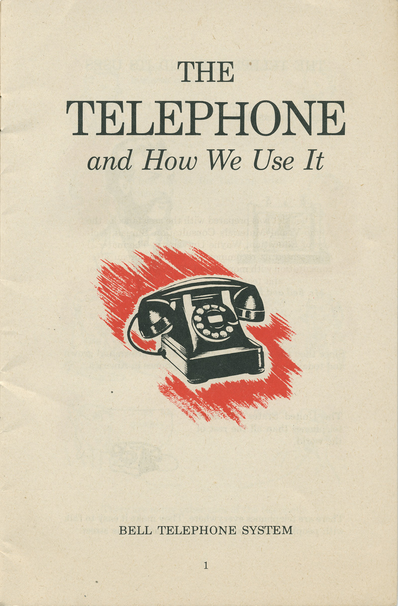
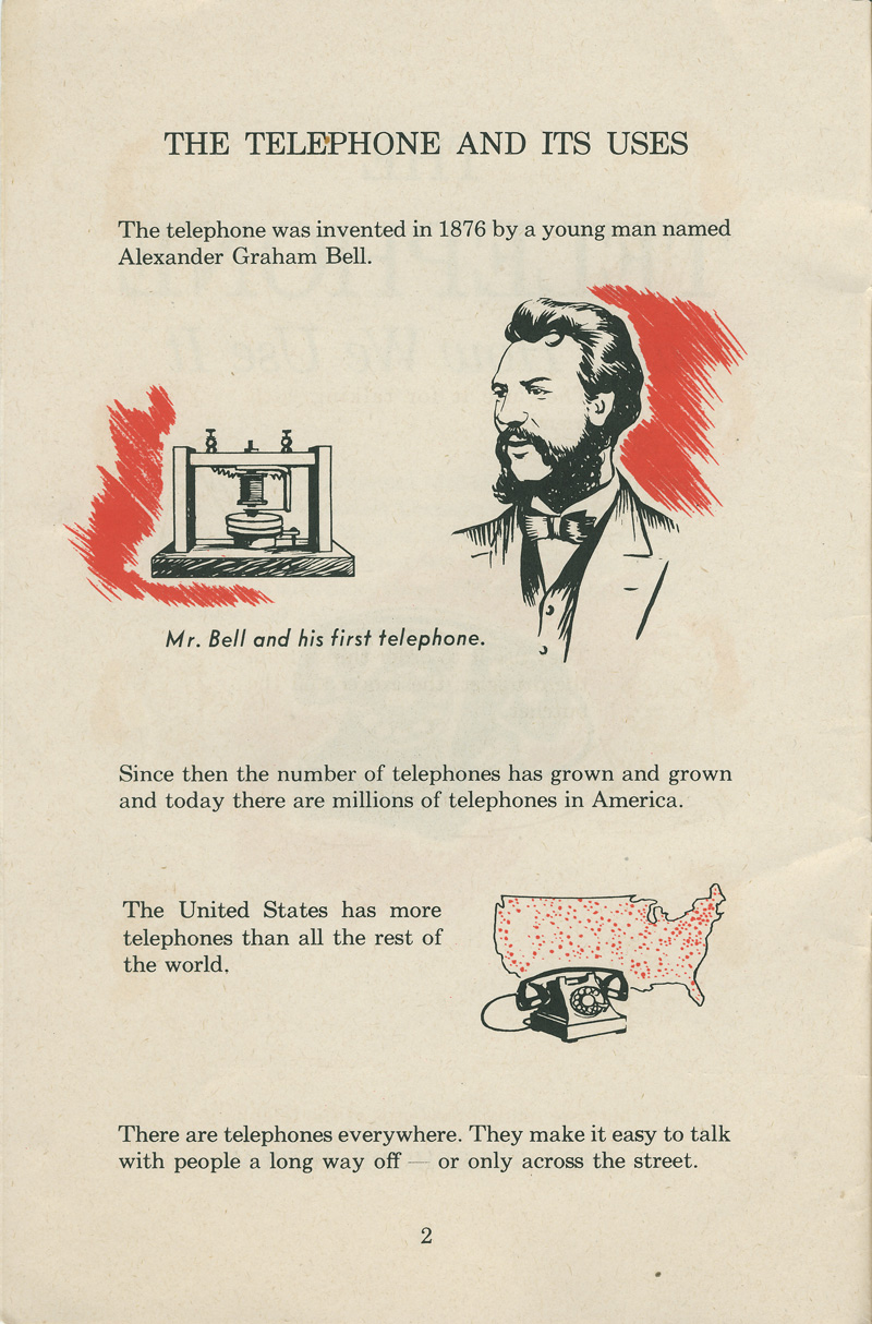
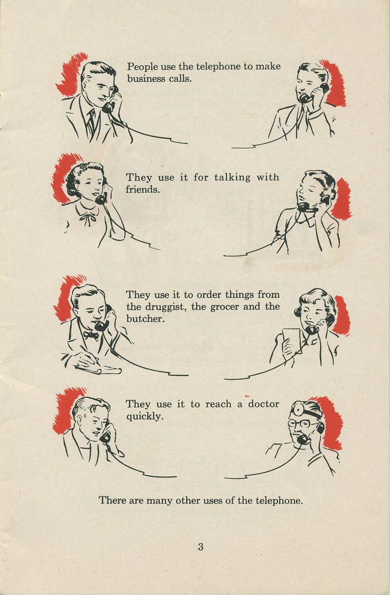
Back in 1951, the Bell Telephone System released a handy booklet called “The Telephone and How We Use It.”
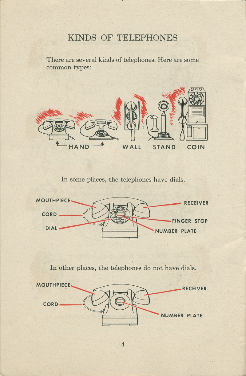
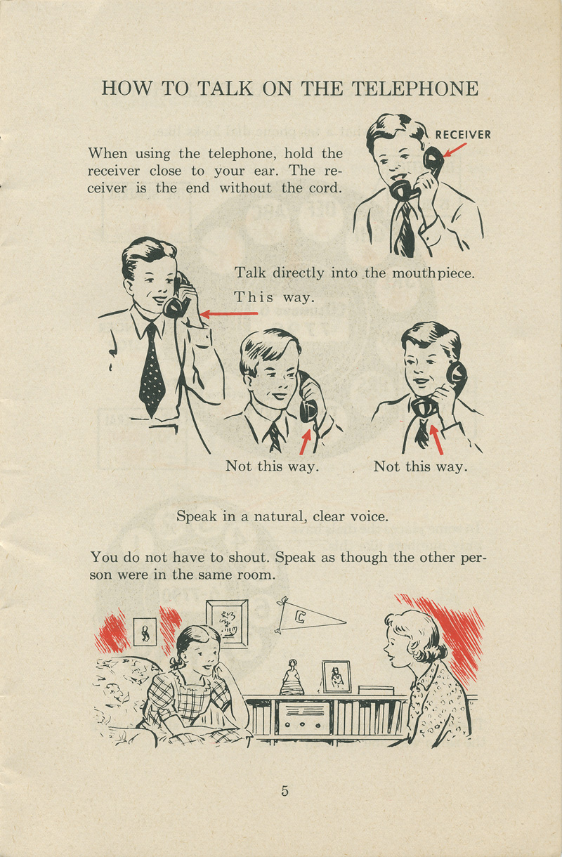
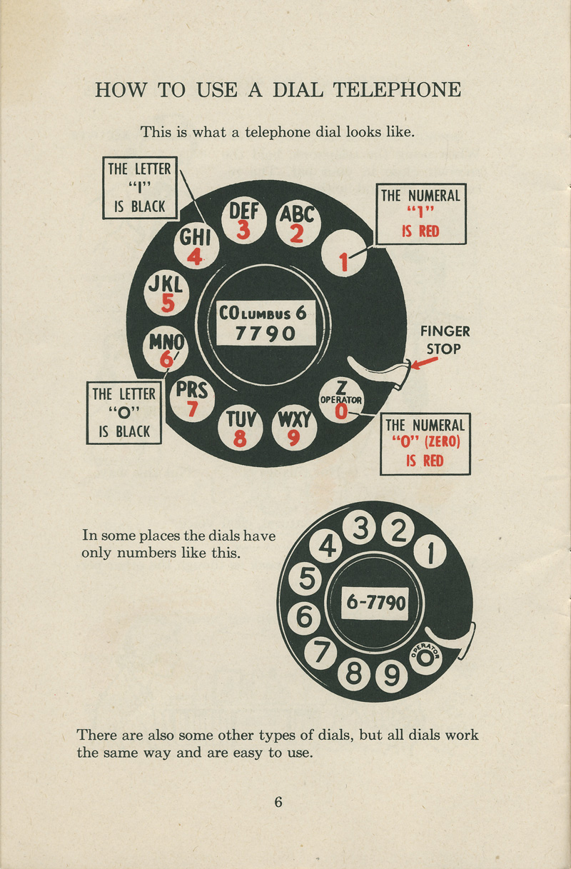
Designed with elementary school students in mind, it was all about helping folks understand the ins and outs of those classic rotary dial phones.
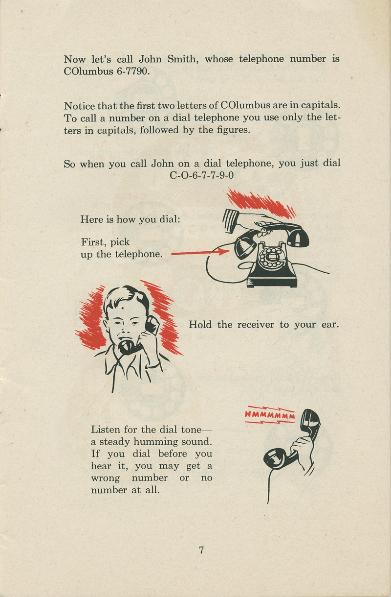
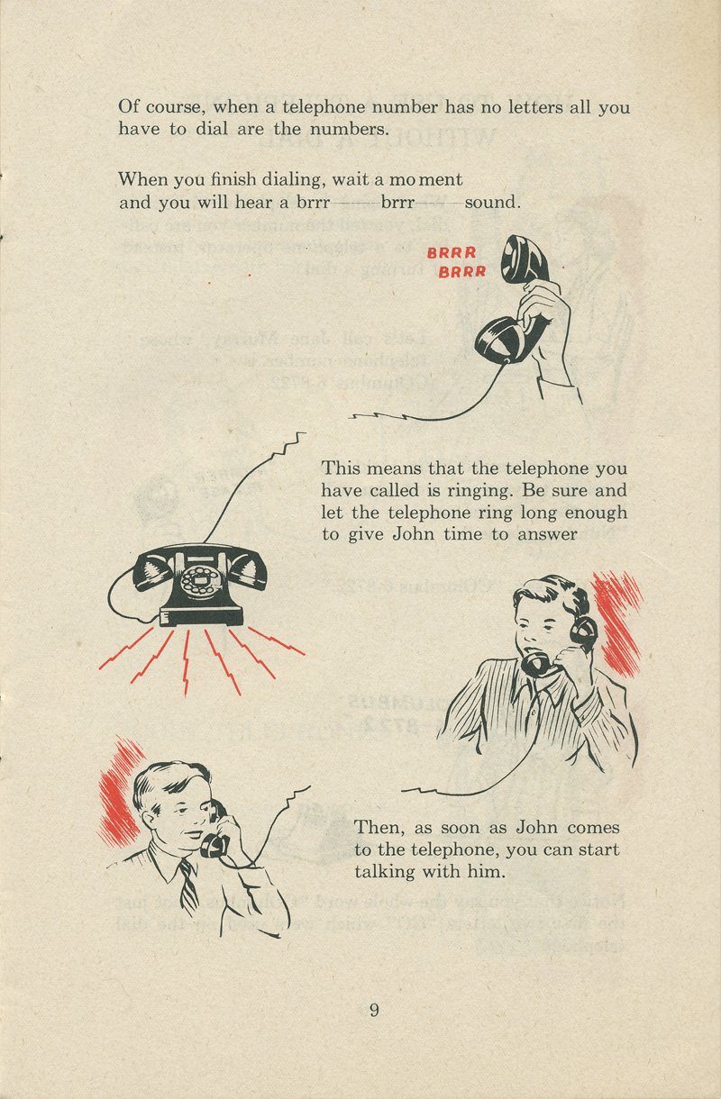
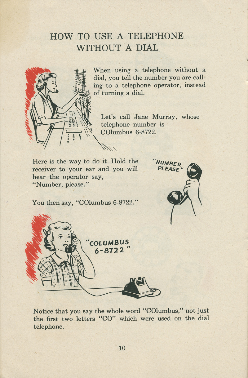
Ever wondered how to use one of those circular dial phones? Or how to start a call and respond when someone rings you up? This booklet had the answers!
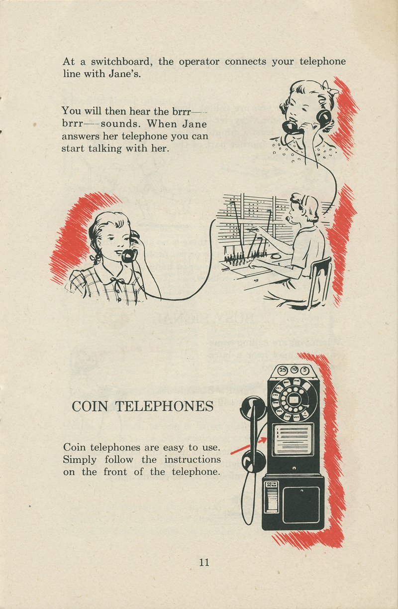
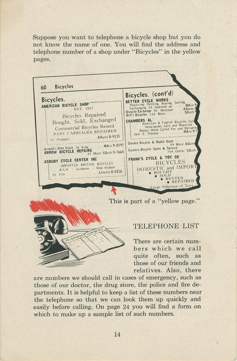
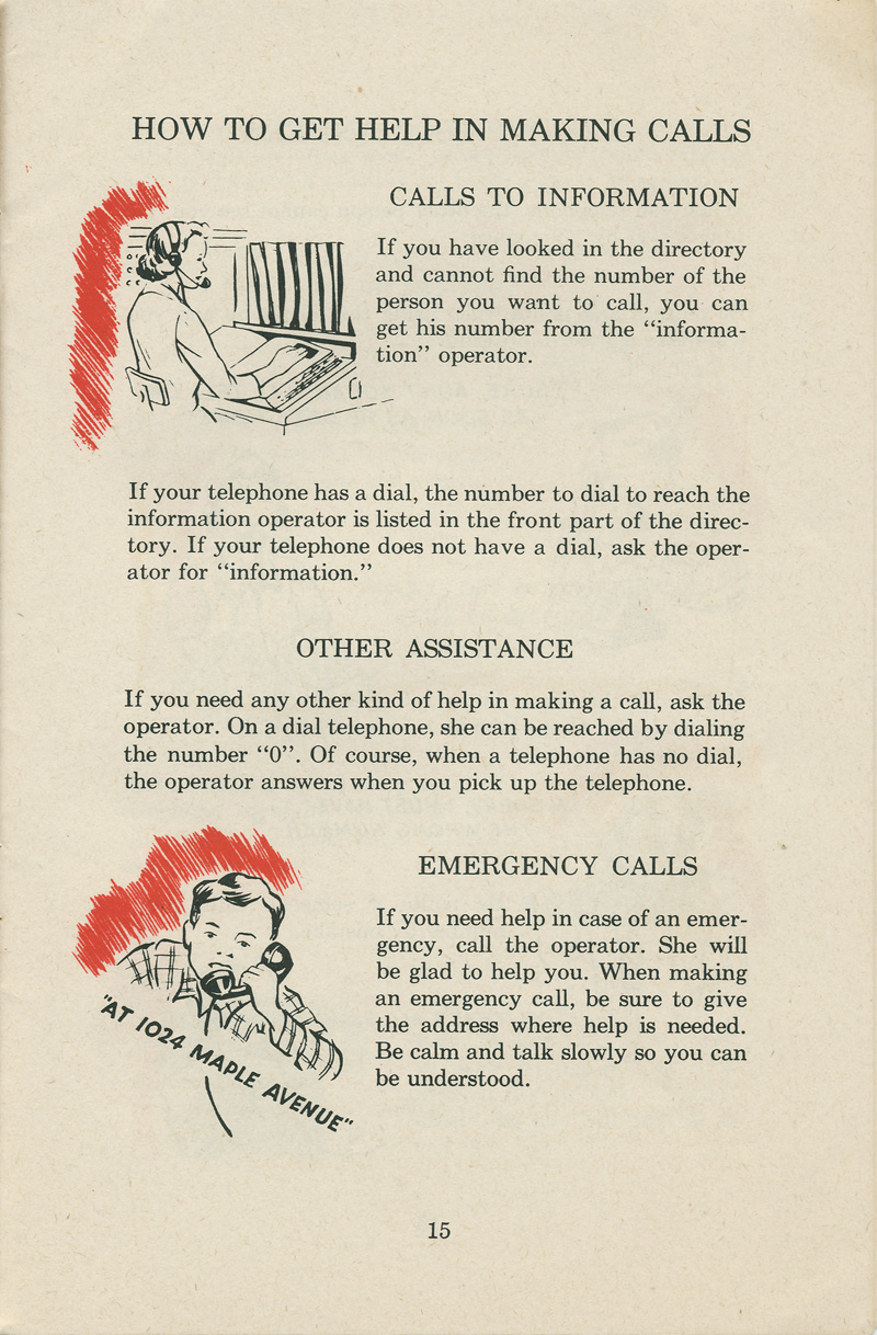
It covered everything you needed to know about these vintage phones, from the basics of making a call to handling emergency situations.
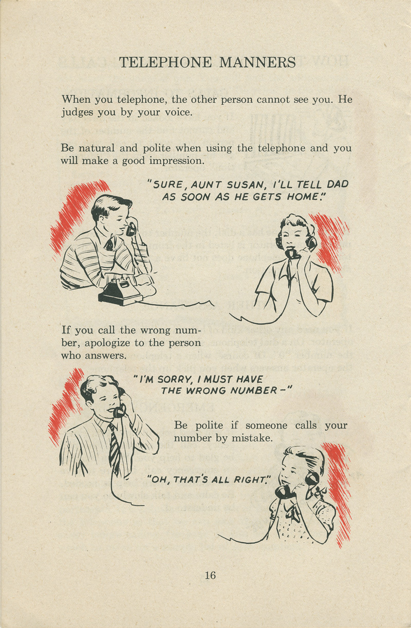
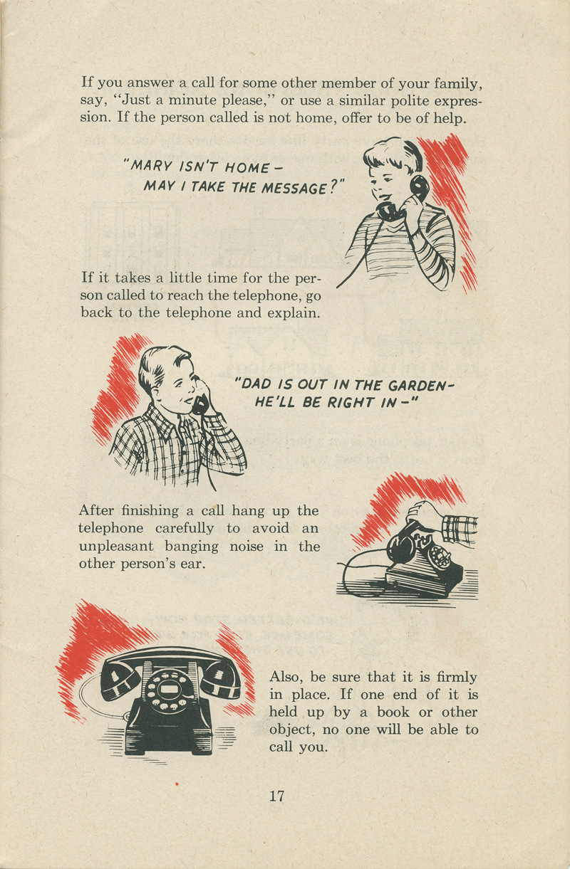
Plus, it gave some helpful tips on polite phone manners, so you could chat like a pro. So, if you ever find yourself in a time warp with a rotary phone, this guide has got you covered!
From as early as 1836 onward, various suggestions and inventions of dials for sending telegraph signals were reported.
After the first commercial telephone exchange was installed in 1878, the need for an automated, user-controlled method of directing a telephone call became apparent.
Addressing the technical shortcomings, Almon Brown Strowger invented a telephone dial in 1891.
Before 1891, numerous competing inventions, and 26 patents for dials, push-buttons, and similar mechanisms, specified methods of signaling a destination telephone station that a subscriber wanted to call.
The early rotary dials used lugs on a finger plate instead of holes, and did not produce a linear sequence of pulses, but interrupted two independent circuits for control of relays in the exchange switch.
The pulse train was generated without the control of spring action or a governor on the forward movement of the wheel, which proved to be difficult to operate correctly.
In the United States, two principal dial mechanisms arose in the engineering laboratories of the largest manufacturers, that of the Western Electric Company for the Bell System, and that of the Automatic Electric Company.
The Western Electric dial had spur gears to power the governor, so the axis of the governor was parallel to the dial shaft.
The Automatic Electric governor shaft was parallel to the plane of the dial at a right angle to the dial shaft.
The governor shaft had worm gearing in which, very atypically, the gear drove the worm. The worm, highly polished, had extreme pitch, with teeth at about 45° to its axis.
The Automatic Electric governor had weights on the middle of curved springs made from strip stock. When it sped up after the dial was released, the weights moved outward, pulling the ends of their springs together.
Springs were fixed to a collar on the shaft at one end and to the hub of a sliding brake disc at the other end. At speed, the brake disc contacted a friction pad.
This governor was similar to that in spring-driven windup phonograph turntables of the early 20th century.
Both types had wrap-spring clutches for driving their governors. When winding the dial-return spring, these clutches disconnected to let the dial turn quickly.
When the dial was released, the clutch spring wrapped tightly to drive the governor.





(Photo credit: ClassicRotaryPhones.com / Wikimedia Commons).
Updated on: September 26, 2023